Information governance exercise
Yorkshire Centre for Health Informatics
HL7 Summer School
Capturing clinical requirements:
Owen Johnson, Senior Fellow, YCHI, Leeds
University
Design Process
Capture clinical
Delegate
Capturing Clinical Requirements A UML Design Process
Learning Objectives • To introduce a light-weight, agile approach to UML design
linking scenarios/ storyboard, semantic modelling, use cases, object oriented analysis, component design and interaction diagrams.
• To overview the science of requirements representation and
how to apply it to healthcare
• To appreciate the art of requirements capture • To review some common tools for working with clinicians. • To get some practical experience applying these techniques
to a case study.
• To reflect on the process of requirements capture.
Source: Business Case for the phased implementation of an e-Prescribing solution from University Hospital of South
Manchester
An agile approach to design
Model the
Model the
"As is" process
"Will be" process
Process Improvement
To what extent are you as a designer looking to improve clinical processes?
• making current care pathways faster and safer • enabling radical improvements in how healthcare is delivered
An agile (and creative) approach to design
2. The Creative Step
Rethink the model
1. Analysis
3. Design
Study and understand
Generate "candidate"
the current solution to
develop a "logical"
design solutions
4. Choose
"Will be"
solution
5. Create prototypes of the Future solution, implement and review
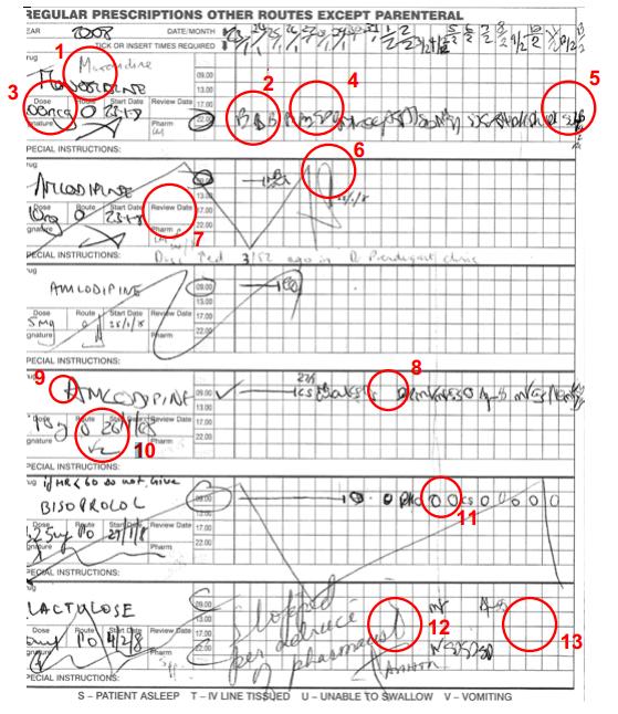
Techniques Storyboard/ User Story/ Scenario
After examining Kari Kidd on the GHH Paediatric Ward, Dr Aaron Attend
decides to prescribe some topical betamethasone (VTM) 0.1% (strength)
for application to a patch of eczema on her wrists (route of administration)
twice a day. This order is entered into the order entry system.
When visiting the ward to review the prescription the pharmacist, Susan
Script, reviews this new prescription and realises it is incomplete, as it is
not fully specified. Following hospital policy from the dermatologists, she
amends the prescription to include a reference to ‘ointment', so that it now
reads betamethasone ointment 0.1% (VMP) topically to wrists (route of
administration) bd. The nurse in charge sends this amended prescription to
pharmacy for supply, which can be filled as it is fully specified.
The Pharmacy Department sends up a 30g tube of betamethasone 0.1%
ointment manufactured by Futuna Ltd, (AMPP), fully labelled for Kari Kidd,
with the dosage instructions etc.
Source: UKCPRS Programme – Dictionary of Medicines and Devices – Use Cases register. Online at
See also Hinchley (2007), pg 21
Techniques Semantic Modelling
Take a scenario, any scenario, and examine it word by word
Verbs = actions/ business processes
Nouns (and Noun Phrases)= Entities in the problem domain
After examining Kari Kidd on the GHH Paediatric Ward, Dr Aaron Attend
decides to prescribe some topical betamethasone
Medical Practitioner
Ward :Ward
: Medication
Dr Aaron Attend:
Kari Kidd :Patient
Exercise 1 Semantic Modelling from a Storyboard
As individuals
Work through the e-prescribing storyboard identifying the interesting verbs and noun phrases.
As a group
2) Create Sticky Note classes for all the nouns and noun phrases
Use Yellow Sticky Notes to represent People or Autonomous Systems
Use Green Sticky Notes to represent any other entity
Tip 1 – the aim is to identify Classes (you can derive/ guess these from instance names, e.g. Kara Kidd is a Patient). Don't worry about instance names just write the name of the class on the Sticky note.
Tip 2 – if you come across adjectives that relate to a Class it can suggest an Attribute of a Class, if your UML is good enough you can write an appropriate attribute name on the Class Sticky.
3) Arrange the Sticky Notes on a flipchart sheet and, thinking about the likely real world relationships,
rearrange the Stickies to create a partial Concept Class diagram for the problem domain.
4) Create Sticky Note Use Cases for each interesting verb
Use Pink Sticky Notes to represent the use case
Tip 3 – Make sure your use case has an active verb and a noun, doing something to something.
5) On a second flipchart sheet, use the Pink Sticky Notes to create a Use Case Diagram if you know how.
Identify at least one Actor for each Use Case.
Tip 4 – To test that your use cases are sound, think about who triggers it and what value it creates for the actor that triggers it.
Exercise Debrief
How hard is this technique
When might this technique be appropriate
Who generates the scenarios
When would you stop
How much technical UML knowledge to you need
How does this fit with HL7 models
Source: Hinchley (2007), page 42. Reproduced without the permission of the author.
Partial solution
Use Case Diagram
prescribed
Prescription Item
Medication
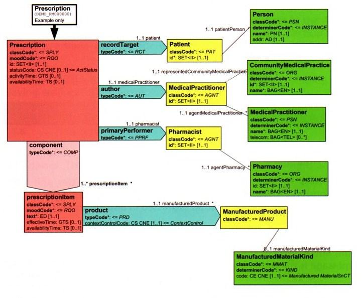
OO Design methods are similar but different to HL7.
Source: Hinchley (2007), page 43. Reproduced without the permission of the author.
A UML-based approach
1) Model Business Processes with Use Cases
5) Model System requirements with
2) Create Concept-level Class
4) Make component
6) Create Design-level
responsibilities for Component
3) Model Business
Processes with Activity
7) Model use case
realisations with
Interaction Diagrams
Use Case Modelling
A Use Case diagram is a simple model of either a
business process or a system requirement.
The principles behind use cases are based on systems theory, any software
component, system, business unit or organisation can be seen as a system which
interacts with people or other systems outside its boundary.
Use Case modelling is based on carefully understanding systems theory.
Use Cases as transactions of value to an actor
Use Case Transactions
At the end of a (successful) use
case the actor should have
received something of value to
them.
Transaction
A series of actions and interactions
which result in an exchange of
items of value, such as information, goods, services and
Use Cases – a Class of transactions
between actor and system
Use Cases are technically a class of transaction between actor and system.
They represent the set of all possible scenarios. The Use Case Diagram is therefore a
type of (concept level) class diagram, it shows actor classes, use case classes and the
relationships between them.
Make an Appointment
The set of scenarios for the above use case might include:
Owen:Patient rings reception for an appointment at 3.30 on Tuesday 7th December
Carol:Patient pops in to make an appointment "any time today"
Simon:Patient agrees with his GP to see her appointment "same time next week"
Sue:Patient makes appointments at 2.15 on 8th December; 9th January and 4th March
Beryl makes an appointment for her mum Gladys:Patient at 4pm on 9th December
Owen:Patient rings to cancel appointment for Tuesday 7th December as he realises he's running a
course that day, he makes an appointment for 3.40pm on Tuesday 14th instead.
Samantha:Patient uses the Internet to book an appointment online for Monday 13th December.
Colin:Patient emails the surgery for an appointment any time Wednesday and they email him back a
time of 4.20 which he confirms is fine.
Each scenario is an instance of the use case performed by an instance of an actor. There are an infinite number of possible scenarios for a use case but they are all essentially following a similar pattern.
Use Case Description As text
Basic Flow is the main flow described in the Use Case Description.
Make an Appointment
This use case begins when Patient decides they want to see a Doctor. They contact the Reception
staff and ask for details of when their preferred Doctor is free. They may discuss a number of
appointment slots that are free before they decide on one that is most convenient for them. They
choose an appointment slot and the Reception staff record the patient's name on the appointment
record and confirm the details back to the Patient.
At the end, the actor is Happy - they get measurable value (Reward > Effort).
Alternate Flows are other variations (alternatives) that still lead to a successful
completion of the use case. The actor is still happy - they still gets measurable
value (Reward > Effort).
Exception Flows are variations that lead to an unsuccessful use case - the user
fails to complete the use case transaction. The actor is NOT Happy - they get no
measurable value and have wasted their time (Effort > Reward).
Primary Actor: (Actor that initiates Use Case)
Other Actors: Value Proposal to Actor(s) (the goal of the Use Case from the
Actor's perspective)
Basic Course of Events:
This use case begins when …
(The Normal Flow)
Alternative Paths: (Other paths through the use case
Alternative Paths
which result in a successful outcome – typically variations to
the basic course of events, determined by the actor and their needs).
Exception Paths: (Other paths through the use case which result in an unsuccessful outcome – typically when
something goes wrong)
Post-conditions:
Related Business Rules:
Related Non-Functional requirements – Usability, Performance, Security: (Any non-functional requirements that are specific to this Use Case rather than the system as a whole)
Project: Author: Date:
Use Case Description as Activity Diagram
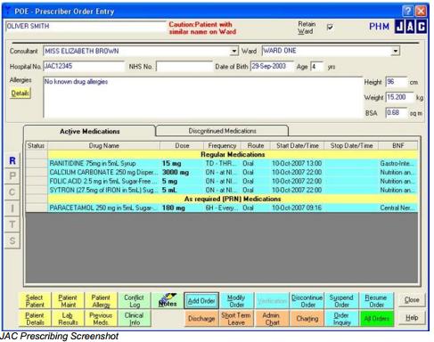
Order Entry
Pharmacy
Decide to Prescribe
Enter Medication
Receive Order from
Order to Pharmacy
Making Implementation Choices
What systems will be used?
Where will they be located? How will they be connected?
What responsibilities should each system have?
How will the systems work together to help realise the use cases?
Order Entry
Pharmacy
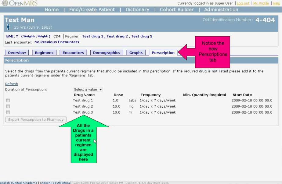
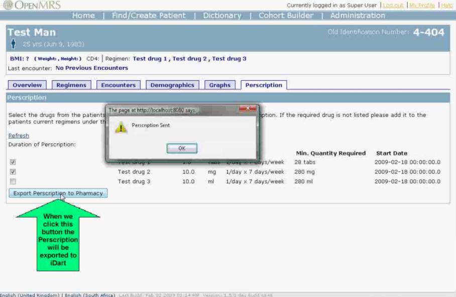
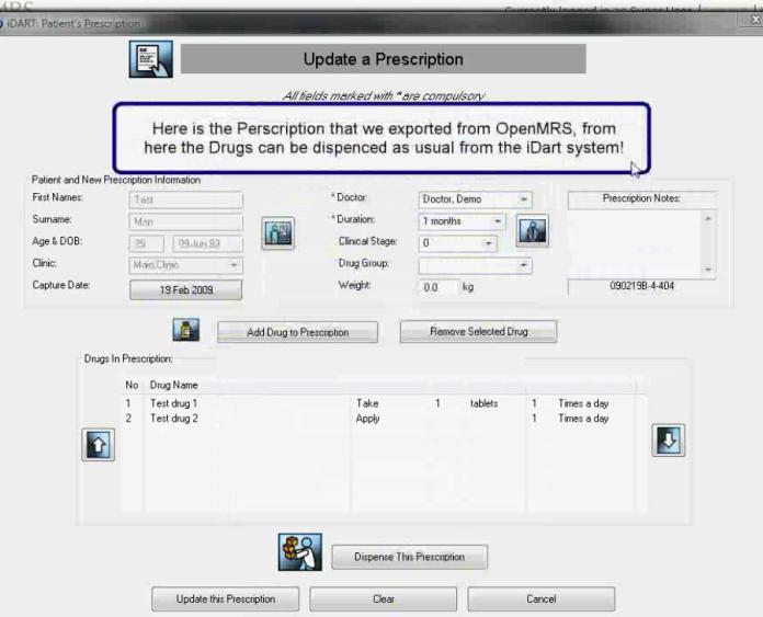
Source: PharmacyExport Module. A brief demonstration of a Pharmacy Export module for OpenMRS. this Module integrates
OpenMRS and the iDart Pharmacy System. http://blip.tv/openmrs/pharmacyexport-module-1822546
Use Case Description as Sequence Diagram
Order Entry
Pharmacy
Pharmacist
Enter Medication Order
Pharmacist
Options for Integration
A) Different systems in different organisations
B) Different systems from different vendors on different servers
HL7 (or something lighter)
Options for Integration
C) Different systems from same vendor
Options for Integration
C) Different modules from same vendor on same server
Enterprise database
D) BUT… No organisation is an island.
A UML-based approach
1) Model Business Processes with Use Cases
5) Model System requirements with
2) Create Concept-level Class
4) Make component
6) Create Design-level
responsibilities for Component
3) Model Business
Processes with Activity
7) Model use case
realisations with
Interaction Diagrams
The Agile Manifesto
Capturing Clinical Requirements A UML Design Process
Learning Objectives • To introduce a light-weight, agile approach to UML design
linking scenarios/ storyboard, semantic modelling, use cases, object oriented analysis, component design and interaction diagrams.
• To overview the science of requirements representation and
how to apply it to healthcare
• To appreciate the art of requirements capture • To review some common tools for working with clinicians. • To get some practical experience applying these techniques
to a case study.
• To reflect on the process of requirements capture.
Yorkshire Centre for Health Informatics
Leeds Institute of Health Sciences Faculty of Medicine and Health Charles Thackrah Building 101 Clarendon Road Leeds, United Kingdom LS2 9LJ Tel. +44 (0) 113 343 4961 www.ychi.leeds.ac.uk
Source: http://www.hl7.org.uk/doc_store/Summer%20School/Day1Session4.pdf
Los Teques MeTro venezuela invests in rePAr: buiLding 8 refinery uniTs AT once brAskeM rAises funds wiTh MegA deAL ciTy of sALvAdor geTs second MArine ouTfALL [ TEO ] Odebrecht Entrepreneurial Technology"Everything we have built will only maintain its value if,
ISSN 2349 – 4425 www.americanij.com The Protective Effect Of Some Natural Antioxidants Against Azithromycin Induced Testicular Dysfunction In Rats El-Dakak, Abeer M. N. H.Ph.D Special Food and Nutrition Dept., Food Technology Research Institute, Agric. Res. Center, Giza, Egypt Email address: [email protected]